Ultra-narrow frame has become a preferred choice for
LED display installations due to its minimal seam gap, high flatness, and easy assembly. Whether you’re assembling an
ultra-narrow LED display frame for commercial use or DIY projects, following a systematic process—
“Accessory Introduction → Main Assembly → Detail Handling → Fixation & Finalization”—ensures efficient and precise frame construction.
Before starting the ultra-narrow frame assembly, open the accessory box to inventory and familiarize yourself with all core components, laying a solid foundation for subsequent operations.
The box contains four aluminum joints and four aluminum corners, both essential for frame connection. The high-strength aluminum joints are specifically designed for corner connection of the ultra-narrow frame, while the aluminum corners undergo laser welding and fine polishing. Their chamfered edges are smooth to the touch (no scratching risk) and match the profile color perfectly, ensuring a uniform frame appearance.
Self-tapping screws are used for fixing joints, connecting plates, and keels, while straight connecting plates serve as key auxiliary parts for frame butt joint. The horizontal and vertical keels, the core support structure of the frame, are made of aluminum with a white cross-section. Their screw holes are prefabricated via precision laser cutting—each horizontal keel has 2 holes on the left and right, and the corresponding vertical keel has 4 holes. Additionally, 4 extra screw holes are arranged on the horizontal rail for segmental splicing of vertical keels.
Auxiliary accessories include foam tape, plastic brackets (for receiver cards), and angle brackets, which respectively serve protective and fixing functions during the ultra-narrow LED frame assembly process.
Main assembly is the core stage of frame formation. It must be carried out in the order of “Frame Butt Joint → Corner Splicing → Keel Installation → Keel Fixation” to ensure stable structure and uniform seams.
First, mark the frame joint positions black with a marker pen. Then fix the aluminum joints with self-tapping screws, install the straight connecting plates, and tighten the screws to complete the frame butt joint. With this technique, the front seam of the frame is only 1 cm wide—extremely narrow and almost invisible—maximizing the overall appearance integrity of the ultra-narrow display frame.
After the frame butt joint, proceed to corner splicing. During operation, hold one side of the frame with your foot to keep it stable, while pushing the corner seams tightly with your hand to ensure close fit. Then use a screwdriver to tighten the screws and firmly fix the 4 aluminum corners. Since the aluminum corners match the profile color, a neatly shaped frame with a uniform visual effect is formed after splicing.
For keel installation, first align the connecting holes of horizontal and vertical keels accurately. The position of horizontal keels can be evenly distributed according to actual needs or adjusted flexibly based on the receiver card installation position.
When fixing, prioritize the holes at both ends of the keels—drill screws into the aligned holes. The joint between horizontal and vertical keels requires 4 screws, which exactly match the 2 holes of the horizontal keel and 4 holes of the vertical keel, ensuring firm connection. If the vertical keel is too short, it can be spliced in segments via the screw holes on the horizontal rail. During splicing, ensure the two segments of vertical keels are at the same height; their flat seams will not affect the overall flatness of the ultra-narrow frame structure.
Notably, the keels are designed in 16 cm grids (32 cm for two grids) and distributed in a “well” shape. There’s no need for additional diagonal processing, simplifying operations while ensuring structural stability.
The profile surface is equipped with auxiliary reference lines. When fixing keels to profiles, drive screws parallel to these lines. The operation sequence is as follows: first fix the side keels to ensure the frame sides are vertical; then align the keels on the other side with the profile reference lines and fix them to form a standard 90-degree right angle; finally, fix the middle keels along the frame edge one by one, using the reference lines as the benchmark. This completes the construction of the entire frame main body.
Although detail handling does not directly determine the frame structure, it is crucial for equipment protection, display effect, and long-term operational stability. Focus on surface protection and frame design details.
Do not tear off the tape on the keels in advance—it does not affect magnet adsorption. If it causes interference during subsequent use, simply cut it open with a utility knife. Meanwhile, attach foam tape to the bottom of the frame. This tape not only insulates the frame but also effectively protects the lamp beads from damage and prevents module sliding—three functions in one for ultra-narrow LED frame maintenance.
An 8 mm inner space is reserved inside the frame. Even if lamp beads are damaged due to collision, they can be hidden inside the frame. Blocking a single lamp bead will not affect the overall display effect. In addition, each module must be adsorbed at the position corresponding to the 16 cm grid. This design maximizes the installation flatness of modules and improves the consistency of the display screen for ultra-narrow border LED displays.
Fixation & finalization is the final stage of assembly, including frame-wall fixation, accessory installation, and overall specification confirmation—marking the completion of the ultra-narrow frame assembly process.
The frame is fixed to the wall using an optimized technique. Instead of traditional angle brackets, directly drill holes with a 12 mm drill bit and drive in M8 expansion screws (fixing hole diameter: 13 mm). This method is simpler to operate and more reliable in fixing effect for DIY ultra-narrow frame installation.
The power supply should be fixed to the side of the keels. Thanks to the holes reserved every 16 cm on the keels, quick positioning during installation is achievable. The receiver card is fixed via a dedicated plastic bracket—install the bracket on the horizontal rail first, then insert the receiver card to complete fixation.
Taking the common 3.84m × 2.24m ultra-narrow frame as an example, it weighs only 30 kg (60 catties), much lighter than traditional steel structure frames. One person can independently complete the entire assembly process, significantly reducing labor costs and operational difficulty for commercial ultra-narrow LED display assembly.
The assembly of ultra-narrow frames relies on precise laser-cut holes and modular design. From accessory preparation to final fixation, each step follows clear standards and operational logic. Following the above process not only ensures the seam precision, structural stability, and display effect of the frame but also enables efficient assembly through simple operations, quickly completing the construction and implementation of the ultra-narrow LED display frame.


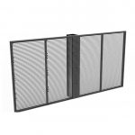


This image showcases the finished 3.84m×2.24m ultra-narrow LED display frame, a lightweight structure weighing only 30kg—much lighter than traditional steel frames. It features minimal visible seams, high flatness, and can be fully assembled by one person, significantly reducing labor costs. The frame is designed for commercial ultra-narrow LED display installations, suitable for retail, advertising, and indoor display scenarios. It embodies the advantages of modular design and precision manufacturing in ultra-narrow frame technology.